The wiring is done and the temptation is to switch on and watch it all work. Not yet. A pump that runs before the circuit is full destroys itself in minutes.
The short answer
The pump is electrically isolated while the circuit is being filled, for one reason: so it cannot run dry. A circulating pump relies on the water passing through it to lubricate and cool the bearings and the seal.
Then the order is fixed and it never changes: look, test dead, energise, make it do its job. The visual inspection comes before any instrument; the interlock test at the end is the one that proves the wiring.
Supplying and isolating the controls
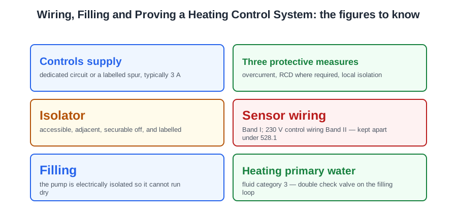
Fixed equipment gets a fixed connection. The controls are supplied either from a dedicated circuit, or from a correctly rated and clearly identified spur — typically 3 A — with a local means of isolation.
Four arrangements are expressly wrong, and each is met on site:
- A 13 A plug in a socket outlet in the airing cupboard. A plug can be unplugged by anyone and is not a fixed connection.
- A feed off the lighting circuit through a junction box. Lighting circuits are protected and sized for lighting.
- A feed off the immersion heater's supply, sharing its isolator, protective device and cabling. Two systems then share one isolation point and one fault.
- An unlabelled spur of any rating, because nobody can tell what it feeds.
The reasoning is the same in every case. A control system is fixed plant that runs unattended for years and is worked on by people who did not install it. It needs a supply of its own, protected at a rating chosen for it, that can be found, switched off and locked off by somebody who has never seen the house before.
The circuit arrangement should incorporate all three of: overcurrent protection of the correct rating; RCD protection where the installation requires it; and a means of local isolation. A surge protective device at the consumer unit is not a substitute for any of them, and an RCD on its own gives no overcurrent protection at all.
The local isolation must be accessible, adjacent to the equipment and securable in the off position. Where the boiler and its controls are fed from one spur, that spur is the local isolation for the control system — but the point of isolation for working on the circuit is still the protective device at the consumer unit, and the two should not be confused.
A heating control system should have only one means of isolation. The classic breach is a frost thermostat fed from a different circuit: an engineer isolates the heating spur, opens the boiler case expecting dead terminals, and finds a live one. A rogue supply like that is re-installed as part of the controlled system.
Regulation 537.2.7 requires every isolation device to be clearly identified. The label does two jobs: it stops the controls being switched off by someone who has no idea what the switch does, and it stops them being switched back on while somebody has the wiring centre apart.
Running the cables
Wiring a control system is mostly cable routes. The terminations take an hour; the routes decide whether the system works, whether it can be serviced, and whether the readings the controller acts on mean anything.
Run the cables while the building is open — first fix: pulled in, clipped, protected and left long. Terminating is second fix. Leaving a cable short is the one mistake first fix cannot recover from, so run generously and coil the surplus at the accessory.
Work from the wiring centre outwards, and label each cable at both ends as you run it, because six identical grey cables in a cupboard are indistinguishable once they are cut.
Sensor cables and mains cables
Controllers act on very small signals from resistance sensors: a cylinder sensor, a collector sensor, an outside sensor for weather compensation. Those signals are easily disturbed. Run a sensor cable alongside a mains cable in the same containment and it can pick up induced interference, producing erratic or drifting temperature readings that make no physical sense.
When a controller shows readings that jump around, suspect the cable routing before you suspect the sensor — replacing a perfectly good sensor is one of the most common wasted call-outs on control systems.
Regulation 528.1 puts a rule behind the habit: a Band I circuit is not contained in the same wiring system as a Band II circuit unless every cable is insulated for the highest voltage present, or the two are in separate compartments of trunking, separated on tray by a partition, or in separate conduit systems. Extra-low voltage sensor wiring is Band I; the 230 V control wiring is Band II.
A sensor cable run across a roof space or out to an external sensor faces three things at once: mechanical protection where it can be stood on or nailed; ultraviolet exposure outdoors, which embrittles ordinary sheathing; and temperature, because a cable near a collector or flue sees far more heat than one in a wall. The current a sensor draws is trivial. The environment is not — neither the cable type nor its protection can be chosen on current alone.
Label the pipework and components as you install them. A modern system has more circuits than the boiler it replaced, and the labelling lets a later engineer identify circuits, isolation points and flow direction without tracing pipes through a floor. It works alongside a system schematic: the label tells you what this pipe is, the schematic tells you where it goes. Mark flow direction on the primaries too — a valve that has to be closed in a hurry is a valve somebody has to identify in a hurry.
Filling
Running a pump dry, even briefly, damages the bearings and seal. It is one of the standard commissioning errors, alongside filling without flushing and letting the pressure relief valve lift during filling. All three come from being in a hurry at the same point in the job, and all three cost more time than they save.
Once the system is full, vented and energised, two things are checked about the pump: that it operates, and that its rotation and flow direction are correct. The direction matters more than it sounds. A pump installed backwards still runs, still sounds completely normal, and still draws roughly its rated current. What it does not do is move water the right way round the circuit — it fights the check valve, delivers nothing, and the symptoms look like a controller or heat source fault. Every pump body carries an arrow: the arrow follows the flow.
The water in a heating primary is not wholesome water. Once inhibitor or antifreeze is in it, it is fluid category 3. So on a sealed system the filling loop assembly carries a double check valve — not an open safety vent, not the cold feed to a feed and expansion cistern, and not the pump outlet. The temporary loop is disconnected after filling.
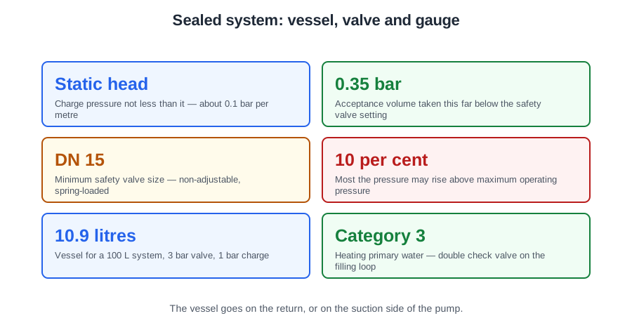
On a sealed system the size of the expansion vessel and its charge pressure are pre-determined by the system designer, so that vessel, relief valve, filling pressure and gauge all work together. Not by the warranty terms, the water undertaker or the building control officer. If you change the system volume, you have changed the designer's assumption, and the vessel has to be reassessed.
And where children, elderly or infirm people are likely to touch the emitters, the choice is a low surface temperature radiator, whose casing keeps the touchable surface far cooler than the water inside — which a standard panel, a cast-iron column or a fan convector does not.
| Step | Why |
|---|---|
| Isolate the pump | So it cannot run dry |
| Flush, then fill through a loop with a double check valve | Debris out, backflow protection in |
| Fill to the designer’s pressure and vent | Vessel and relief valve work as designed |
| Energise and check pump rotation and direction | A backwards pump looks like a controller fault |
The visual inspection
Any visual inspection must always come before testing with instruments, and on a control system it finds most of the faults there are.
That is not a slur on instruments — it is simply where the faults live on this kind of work. A control system is dozens of small terminations in half a dozen enclosures, made in poor light with the cores all much the same length. The faults are a core in the wrong terminal, a strand sticking out, a sleeve that never went on, a cable resting on a hot pipe. An ohmmeter will find some of those eventually. A slow look finds all of them in ten minutes.
The items from Regulation 642.3 that bite on a control installation:
- Connection of conductors — every core securely clamped, no bare copper outside the terminal, no insulation trapped under a screw, no strands escaping.
- Identification of conductors — brown line, blue neutral, green-and-yellow sleeving on every bare protective conductor.
- Routing of cables in prescribed zones, or protection against mechanical damage.
- Connection of single-pole devices in line conductors only — incorrect polarity is often visible before it is measured.
- Correct connection of accessories and equipment, and protection against thermal effects.
Incorrect polarity is easily identified during a simple visual inspection, where a neutral or earth conductor has been put in the wrong terminal. The remedy is to safely isolate, verify the supply polarity, and refit the conductors into the proper terminals as marked — not to leave it for the instrument to find later.
On a wiring centre, work along the block one terminal at a time, reading the printed legend and then the core, rather than checking the cables one by one and trusting the pattern. A valve orange landed on a neutral terminal is a fault that will not announce itself politely.
On an existing installation you will meet burnt connections. If a conductor and its insulation have been scorched, that must be remedied before any certification is produced. Find the cause: a loose termination or a reduced conductor area gives high resistance, and the high resistance makes the heat. Usually both the conductor and the component are replaced.
The rest of the walk round: covers secure with no open knockouts; grommets and glands; cables supported on metal clips or saddles with nothing hanging on its terminations; cables clear of the primary pipework; sleeving on every bare cpc, including inside the wiring centre; the isolator and the bonding clamps labelled; valve heads free to move and their flexes not stretched.
Any damage, installation error or defect found must be made good before any certificate is issued.
Testing dead
The earth continuity test confirms that all appropriate parts are earthed. That is its whole purpose — not polarity, not insulation, not supply voltage. On a control system that means every exposed metal part that could become live: the boiler casing, the pump body, the valve bodies where they are Class I, the metal enclosure of any accessory.
The measurement is made with a low-resistance ohmmeter whose leads have been nulled. On a radial circuit: link line and cpc at the origin, measure between the incoming line and cpc terminals at the far end — a very low reading proves continuity and gives R1+R2 — then remove the link and test again: a high reading proves you tested the right circuit.
Polarity verifies that the fuse and any single-pole switch sit in the line conductor only, and that everything downstream is the right way round. Check core by core against the wiring centre's printed terminals, because the plate does not care whether the brown wire you pushed into the boiler live terminal actually comes from the line side of the fuse.
Insulation resistance is tested at 500 V DC with a minimum of 1 MΩ. A finished control system is full of electronics, so either disconnect that equipment, or make only a measurement between the live conductors connected together and the earthing arrangement. What you never do is apply the test voltage across an electronic board that will be damaged by it — and what you never do is skip the test and record it as not applicable.
Where a specific device is suspect the test is different. A zone valve that will not open has two likely causes: the controlling thermostat has failed, or the servo motor has burnt out. Once the wiring is visually confirmed, a dead test for resistance across the motor leads settles it — there should be a reading, and infinity or OL means the winding is open circuit.
Results are written down as they are taken, on the schedule of test results: R1+R2 or R2, insulation resistance live-to-live and live-to-earth, polarity satisfactory, and after energising the measured Zs and any RCD result. Results remembered and written up in the van are not results.
Functional testing and the interlock
Regulation 643.10 requires equipment to be functionally tested to verify that it is properly mounted, adjusted and installed and operates correctly — its examples include controls and interlocks, which is exactly a heating control system.
So these are functional tests: the programmer switches the boiler on at the set time; a motorised valve drives open when called; two-way switches operate a light from both positions. And this is not: checking that circuit breakers operate under short circuit conditions. Nobody creates a short circuit to test a breaker — its breaking capacity is a matter of selection, verified by the design and the manufacturer, not by an act on site.
The sequence on a heating system:
- Hot water only. The cylinder valve should drive open, and only then should the boiler and pump start.
- Heating only. The heating valve drives open; boiler and pump run.
- Both on, and confirm both circuits are served.
- Turn the room thermostat below room temperature. Its valve should close and, if the cylinder is satisfied too, the boiler and pump must stop. That is the interlock, and it is the test that proves the wiring.
- Turn the cylinder thermostat down and confirm the same on that circuit.
- Check the pump runs and, where the boiler has pump overrun, that it continues briefly after the burner stops.
- Where a frost thermostat is fitted, confirm it brings the boiler and pump on with the programmer off, and that the pipe thermostat is in circuit with it.
Protective devices are functionally tested too: where an RCD provides fault or additional protection, the effectiveness of its integral test button is verified.
Commissioning is the setting up and proving of the whole system, not just the electrics: balancing, flow temperatures, control settings, and the manufacturer's checks. The approved procedures are those in the Domestic Building Services Compliance Guide.
Where a building notice or full plans have been given to a local authority, the notice of completion of commissioning goes to the building control body within five days. Where the work is done under a competent person scheme, within 30 days.
At handover the customer gets the electrical certificate and schedules, the commissioning record and manufacturer's instructions, a system schematic showing circuits, valves and isolation points, and a demonstration of the programmer, the thermostats and how to isolate the system. Then walk them through it once, in their own kitchen, and leave the labels where you fitted them.
🔢 The numbers worth memorising
- Controls supply
- dedicated circuit or a labelled spur, typically 3 A
- Three protective measures
- overcurrent, RCD where required, local isolation
- Isolator
- accessible, adjacent, securable off, and labelled
- Sensor wiring
- Band I; 230 V control wiring Band II — kept apart under 528.1
- Filling
- the pump is electrically isolated so it cannot run dry
- Heating primary water
- fluid category 3 — double check valve on the filling loop
- Vessel size and charge
- fixed by the system designer
- Insulation resistance
- 500 V DC, minimum 1 MΩ
- Suspect valve motor
- dead resistance test — infinity means an open winding
- The interlock test
- both stats satisfied → boiler and pump stop
- Notice of commissioning
- 5 days under a building notice, 30 days under a scheme
⚠️ Where people go wrong
- Feeding the controls from a plug, the lighting circuit or the immersion supply.
- Leaving the spur unlabelled.
- Treating an RCD as overcurrent protection.
- Leaving a frost stat on its own circuit. One system, one means of isolation.
- Running sensor cable alongside mains cable, then replacing a perfectly good sensor.
- Choosing an external sensor cable on current alone. It is protection, UV and temperature.
- Running a pump before the circuit is full.
- Fitting a pump backwards. It runs, sounds normal, draws its current and moves nothing.
- Putting the double check valve anywhere but the filling loop.
- Changing the system volume without reassessing the vessel.
- Reaching for an instrument before looking. Most control faults are visible.
- Leaving polarity for the meter when the wrong terminal is plain to see.
- Certifying scorched terminals, or replacing the burnt part without finding the cause.
- Recording insulation resistance as not applicable because of the electronics.
- Calling a short-circuit test on a breaker a functional test.
- Skipping the interlock test. It is the one that proves the wiring.
- Writing the results up in the van.
📝 10-Question Self-Test
Straight from the Level 3 course question bank. Click an option to see whether you got it right — the explanation appears instantly, and there is nothing to submit.
Replace the cable and reroute the new one away from the pipe. That is the only answer that deals with both halves of the problem: the damage already done, and the heat source still there. BS 7671 Regulation 522.2.1 requires a wiring system to be protected from external heat by shielding, distance, a suitable cable type or reinforced insulation. Self-amalgamating tape is not a permitted way of making good insulation and leaves the cable on the pipe.
Electrical installation work in a dwelling is BS 7671 work: Approved Document P paragraph 1.1 says electrical installations should be designed and installed in accordance with BS 7671, and MIS 3005-D lists BS 7671 among its reference publications rather than displacing it.
BS 7671 Regulation 641.1 requires every installation to be inspected and tested during erection and again on completion, before it is put into service. Inspecting as the work goes is the only way to see anything that will later be buried in a wall or a duct. Waiting until the installation is energised is too late; Regulation 642.1 has inspection done with that part disconnected.
Operating a circuit breaker under short circuit conditions is not a functional test — it is a destructive check of a protective device, verified by its type and rating rather than by tripping it on site. BS 7671 Regulation 643.10 requires functional testing to verify that equipment is properly mounted, adjusted and installed and operates correctly: a programmer switching at the set time, a valve driving open, two-way switching working from both ends.
To confirm that all appropriate parts are earthed — that there is an unbroken low-resistance path from every piece of exposed metalwork back to the main earthing terminal, so a fault current can operate the protective device. BS 7671 Regulation 643.2.1 puts it as continuity of protective conductors, verified by measuring resistance. Insulation breakdown is a different test, made with an insulation resistance tester at 500 V.
It has to run, and it has to move fluid the right way round the circuit. A pump installed backwards will still run and still sound normal, but it fights the check valve and delivers nothing — which then looks like a collector or controller fault.
Fixed equipment gets a fixed connection: correct overcurrent protection, RCD protection where required, and a local means of isolation so the system can be serviced without disturbing anything else. A 3 A fused spur is the usual arrangement, and it must be labelled to show what it feeds.
An unlabelled spur is a circuit nobody can identify. The label is what stops the solar controls being switched off and forgotten — or switched back on while somebody has the pump station apart.
A heat pump installation has more circuits than the boiler it replaced — primary, brine or external water, cylinder primary, buffer connections, several isolation points. Clear labelling, supported by a schematic in the handover pack, saves an engineer considerable time and prevents the wrong valve being closed.
The current is trivial; the environment is not. A sensor cable near a collector sees high temperatures, and any external section sees sunlight — so both the cable type and its protection have to suit, or it degrades and the controller loses its most important input.
Going further: the lessons behind this article
This article is the public answer. Unit 333 of the Level 3 course takes the same ground to the depth the exam and the synoptic assignment ask for, in 6 lessons:
- Supplying and isolating the controls on site
- Running the cables and wiring the control system
- Filling the system before the controls are proved
- Visual inspection of the completed controls
- Testing the finished controls: earth continuity and polarity
- Functional testing, commissioning and handover
- Central heating systems: the Unit 333 guide — every article on this unit in one place
- All PlumbMate articles — Level 1, 2 and 3
- The Level 3 course — the whole 8202-35 Diploma